เครื่องทดสอบฉนวน
Insulation Testers
INSULATION TESTERS
Digital Insulation Testers for PV Systems, 5-range
|
|
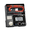
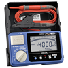
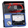
INSULATION TESTER IR4053Digital Insulation Tester for Photovoltaic Generation Systems
• Built-in PV dedicated function • 600 V AC/ 1000 V DC meter • 5 test voltage ranges from 50 to 1000 V • Comparator function
|

High-voltage Digital Insulation Testers | 5 kV Insulation Testers
|
|
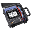
HIGH VOLTAGE INSULATION TESTER IR3455Maximum 5kV Test Voltage – Up to 10TΩ of Insulated Resistance Testing
• 5 high voltage ranges • 250/500/1k/2.5k/5k V testing voltages • Leak current, voltage, temperature, insulation resistance testing, data memory • Integrated hard carrying case
|
Digital Insulation Testers, 5-range
|
|
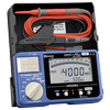
INSULATION TESTER IR40585-Range, 50 to 1000V Digital Insulation Tester with Continuity Check
• 5 ranges from 50 to 1000 V • 600 V AC/DC meter • 200 mA continuity check • Built-in Bluetooth® wireless technology
|
|
|
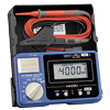
INSULATION TESTER IR40565-Range, 50 to 1000V Digital Insulation Tester with Continuity Check
• 5 ranges from 50 to 1000 V • 600 V AC/DC meter • 200 mA continuity check
|
|
|
INSULATION TESTER IR40575-Range, 50 to 1000V Digital Insulation Tester with Continuity Check
• 5 ranges from 50 to 1000 V • 600 V AC/DC meter • 200 mA continuity check
|
Analog Insulation Testers, 3-range
|
|
ANALOG MΩ HiTESTER 34903-Range, 250 to 1000V Analog Insulation Tester with Continuity Check
• 3 ranges: 250/500/1000 V • 200 mA continuity check • AC voltage testing
|
Analog Insulation Testers, Single-range
|
|
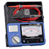
ANALOG MΩ HiTESTER IR4017Single-Range 500V/1000MΩ Analog Insulation Tester
• Single range: 500 V/ 1000 MΩ • AC voltage testing
|
|
|
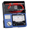
ANALOG MΩ HiTESTER IR4016Single-Range 500V/100MΩ Analog Insulation Tester
• Single range: 500 V/ 100 MΩ • AC voltage testing
|
|
|
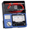
ANALOG MΩ HiTESTER IR4018Single-Range 1000V/2000MΩ Analog Insulation Tester
• Single range: 1000 V /2000 MΩ • AC voltage testing
|
This page describes the objective of insulation resistance test and outlines some standard values for insulation resistance. It also provides a detailed description of how to measure insulation resistance with an insulation tester and how to utilize various instrument functions.
00. How to Use Digital Insulation Resistance Meters – Basic Course
-
How to Use Digital Insulation Resistance Meters – Basic Course
-
This video explains how to use a digital insulation resistance tester to measure a distribution panel. ※ Shooting was done with Japanese model IR 4052. The global model name is IR 4057.
01. What is insulation resistance testing?
-
Purpose of insulation resistance testing
-
Portable insulation resistance testers and megohmmeters are designed to help prevent hazards such as electric shock and short-circuits caused when the insulation in electrical devices, parts, and equipment used in industrial plants, buildings, and other settings degrades over long periods of use.
Degradation of the insulation between charged and non-charged portions of electrical devices and equipment utilizing the type of structure illustrated in Figure 1 on the right poses the risk of a ground fault or electric shock. Degradation of the insulation between two or more charged potions as shown in Figure 2 poses the risk of a short-circuit.
Higher insulation resistance values indicate more effective insulation.
-
Insulation testers: Rated standard measurement voltage and example uses
- When using an insulation resistance tester to measure insulation resistance, Japanese standards* require certain voltage values to be applied by the instrument for certain measurement targets, as shown in the table on the right.It is necessary to select from the multiple application voltage values (rated measurement voltages) that are provided by the insulation resistance meter based on the target:
Single-range insulation testers: Insulation resistance meters that can only generate one rated measurement voltage
Multi-range insulation testers: Insulation resistance meters that can generate two or more rated measurement voltages
Since different insulation testers provide different combinations of rated measurement voltages, it is necessary to choose an instrument that provides the combination of values that is best suited to the application at hand.
-
-
Criteria for measured insulation resistance values
-
In Japan, Article 58 of the Technical Standards of Electric Installation sets forth the following insulation resistance values for a variety of circuit operating voltage categories:
Conductor-to-ground voltages that are less than 150 V: 0.1 MΩ
Conductor-to-ground voltages that are greater than 150 V and less than or equal to 300 V: 0.2 MΩ
Conductor-to-ground voltages that are greater than 300 V: 0.4 MΩHowever, it is desirable that newly installed equipment yield a measured insulation resistance value of at least 1 MΩ.
02. Insulation Tester Principles
-
Principle of insulation-resistance measurement as implemented by insulation testers
-
The insulation resistance Rx of the measurement target is calculated by measuring the current I that flows to the target when the voltage V is applied and then dividing the applied voltage V by the resulting current I.
-
Principle of low-insulation-resistance measurement as implemented by insulation testers
-
The insulation resistance Rx of the measurement target is calculated by measuring the voltage V that occurs across the measurement terminals when the current I is applied to the target and then dividing the terminal voltage V by the applied current I.
-
Principle of photovoltaic resistance measurement as implemented by insulation testers
-
The resistance Rx of the measurement target is calculated by measuring the current I that flows to the target when the voltage V is applied and then dividing the applied voltage V by the resulting current I. (The voltage and current values produced by the measurement target as it generates electricity are subtracted.)
03. How to use insulation testers
-
Components of an insulation tester
-
The figure on the right illustrates the name of each part of the Hioki Insulation Tester IR4057.
-
Insulation resistance measurement
-
Warning: Do not attempt to measure insulation resistance on a live conductor.
・ Verify that the MEASURE key is not in the raised position ([1] in figure on the right).
・ Consult the table and determine the measurement voltage to which to set the rotary switch ([2] in figure on the right).
・ Connect the black test lead to the ground side of the object being measured. [3]
・ Connect the red test lead to the line to be measured. [4]
・ Press the MEASURE key. [5]
・ Read the value after the inductor has stabilized. [6]*This list provides an overview of how to use insulation testers. Please consult the user manual for your product to ensure safe and proper use.
*Please note that values in the table apply to testing in Japan. -
Discharging function
-
To properly discharge, be sure to perform as shown below after the measurement.
・ Without removing the test leads from the item being measured, release the MEASURE key.
・ The built-in discharge circuit automatically discharges the item.
・ The discharge will end when the “discharge mark” on the right side of the display disappears.*This list provides an overview of how to use insulation testers. Please consult the user manual for your product to ensure safe and proper use.
*Please note that values in the table apply to testing in Japan.“Product List” of the insulation testers, please refer to here. -
Voltage measurement
-
Notes: Test leads should only be connected to the secondary side of a breaker.
Never press the MEASURE key while measuring voltage.・ Use the rotary selector to select the V function.
・ Connect the black test lead to the ground side of the object being measured.
・ Connect the red test lead to the line side of the breaker.
・ Read the value after the indicator has stabilized.*This list provides an overview of how to use insulation testers based on the Hioki Model IR4057. Please consult the user manual for your product to ensure safe and proper use.
*Please note that values in the table apply to testing in Japan. -
Resistance measurement
-
Before measurement, perform zero adjustment to cancel the test leads’ wiring resistance and other potentially problematic quantities.
・ Set the rotary selector to the Ω function.
・ Short circuit the tip of the test lead.
・ Pull up the MEASURE key.
・ Turn off the MEASURE key to hold the measured value.
・ Press the “0Ω ADJ” key.
・ Connect the test lead to the ground side of the object being measured
・ Press MEASURE key and read the displayed value.
・ Turn off the MEASURE key after using.
The figure is an example of checking the continuity of ground wiring.*This list provides an overview of how to use insulation testers based on the Hioki Model IR4057. Please consult the user manual for your product to ensure safe and proper use.
*Please note that values in the table apply to testing in Japan. -
PVΩ measurement (Insulation Tester IR4053 only)
-
PVΩ measurement is used to measure insulation resistance between a solar panel and ground. The PVΩ measurement allows accurate resistance measurements without the effect from power generation.
・ Turn OFF the main switch to the connection box to be discontinued from the power conditioner.
・ Turn OFF all disconnect switches used for strings.
・ Check that MEASURE key has been turned OFF. [1]
・ Set the rotary switch to “PVΩ”.
・ Press the PVΩ 500V⇔1000V key and set the voltage to 500 V or 1000 V. [3]
・ Press the “500V/1000V RELEASE” key to release the lock. [4]
・ Connect the black test lead to the ground terminal. [5]
・ Connect the red test lead to terminal P of the string. [6]
・ Press the MEASURE key. [7]
・ A resistance will be indicated after approximately four seconds. [8]
・ Turn OFF the MEASURE key. [9]
・ If there is no deteriorated insulation performance found with terminal P measurement, connect the red test lead to the terminal N of the string to measurements by procedures from [7] through [9].*This list provides an overview of how to use insulation testers based on the Hioki Model IR4053. Please consult the user manual for your product to ensure safe and proper use.
*Please note that values in the table apply to testing in Japan.