Meter Relays/CTs/Shunts
IMPEDANCE ANALYZERS & LCR METERS
Impedance Analyzers, up to 3 GHz
|
|
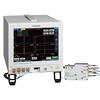
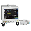
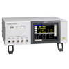
IMPEDANCE ANALYZER IM75871MHz to 3GHz Measurement Frequency Impedance Analyzer with 0.5ms Test Speed and 0.07% Variability
• |Z|, L, C, R testing • Testing source frequency: 1 MHz to 3 GHz • Measuring time: 0.5 ms • Measure LCR and conduct frequency sweeps simultaneously
|
|
|
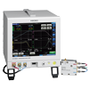
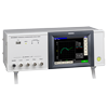
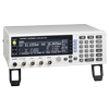
IMPEDANCE ANALYZER IM7580A1MHz to 300MHz Measurement Frequency Impedance Analyzer with 0.5ms Test Speed and Superior Repeatability
• |Z|, L, C, R testing • Testing source frequency: 1 MHz to 300 MHz • Measuring time: 0.5 ms • Measure LCR and conduct frequency sweeps simultaneously
|
|
|
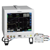
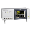
IMPEDANCE ANALYZER IM7581100kHz to 300MHz Measurement Frequency Impedance Analyzer with 0.5ms Test Speed
• |Z|, L, C, R testing • Testing source frequency: 100 kHz to 300 MHz • Measuring time: 0.5 ms • Measure LCR and conduct frequency sweeps simultaneously
|
|
|
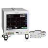
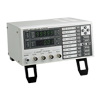
IMPEDANCE ANALYZER IM75851MHz to 1.3GHz Measurement Frequency Impedance Analyzer with 0.5ms Test Speed and 0.07% Variability
• |Z|, L, C, R testing • Testing source frequency: 1 MHz to 1.3 GHz • Measuring time: 0.5 ms • Measure LCR and conduct frequency sweeps simultaneously
|
|
|
IMPEDANCE ANALYZER IM75831MHz to 600MHz Measurement Frequency Impedance Analyzer with 0.5ms Test Speed
• |Z|, L, C, R testing • Testing source frequency: 1 MHz to 600 MHz • Measuring time: 0.5 ms • Measure LCR and conduct frequency sweeps simultaneously
|
|
|
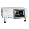
CHEMICAL IMPEDANCE ANALYZER IM3590For R & D applications of Electrochemical Components and Materials, Batteries, and EDLCs
• |Z|, L, C, R, σ, ε testing • Battery measurement • 1 mHz to 200 kHz • 2 ms measurement time
|
|
|
EQUIVALENT CIRCUIT ANALYSIS FIRMWARE IM9000Simple Circuit Analysis & Detailed Acceptance/Rejection Decision-Making
• Optional software for Model IM3570 • 5 equivalent circuit models • Plot frequency characteristics graph from analysis results • Cole-Cole plot, admittance circle display
|
|
|
IMPEDANCE ANALYZER IM3570Single Device Solution for High Speed Testing and Frequency Sweeping
• |Z|, L, C, R testing • 4 Hz to 5 MHz • 0.5 ms measurement time • Measure LCR and conduct frequency sweeps simultaneously
|


LCR Meters, up to 8 MHz
|
|
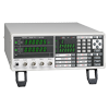
LCR METER IM3536DC, or 4 Hz to 8 MHz
• |Z|, L, C, R testing • DC, or 4 Hz to 8 MHz • Accuracy guaranteed range from 1mΩ
|
|
|
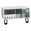
LCR METER IM3523|Z|, L, C, R testing
• |Z|, L, C, R testing • Testing source frequency: 40 Hz to 200 kHz • Measuring time: 2 ms
|
|
|
LCR METER IM35331 mHz to 200 kHz
• |Z|, L, C, R testing • Testing source frequency: 1 mHz to 200 kHz • Transformer measurement mode
|
|
|
LCR HiTESTER 3511-50|Z|, L, C, R testing
• |Z|, L, C, R testing • Testing source frequency: 120 Hz or 1 kHz • Measuring time: 5 ms
|
Capacitance Meters, up to 1 MHz
|
|
C METER 3506-10C, D, Q, low capacitance testing
• C, D, Q, low capacitance testing • 1 kHz, 1 MHz • 1.5 ms measurement time at 1 MHz
|
|
|
C HiTESTER 3504C, D, large capacitance MLCC testing
• C, D, large capacitance MLCC testing • 120Hz or 1kHz • 2 ms measurement time
|
Test fixture or Probes
|
|
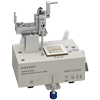
SMD TEST FIXTURE IM92013GHz High Frequency Test Fixture for 6 Different SMD Sizes
• Direct connection two-terminal measurement type • DC to 3 GHz • Measurable sample sizes: 0201 to 1210 (EIA)
|
|
|
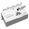
SMD TEST FIXTURE IM9110High-precision two-terminal fixture for measuring ultra small “008004” (EIA) components
• Direct connection two-terminal measurement type • DC to 1 MHz • Measurable sample sizes: 008004 (EIA)
|
|
|
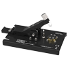
SMD TEST FIXTURE IM9100High-precision four-terminal measurement for ultra small size 01005 (EIA)
• Direct connection type • SMDs with electrodes on the bottom • DC to 8MHz • Measurable sample sizes: 01005 to 0402 (EIA)
|
|
|
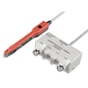
PINCHER PROBE L2001Measurement for small size “0603” (EIA)
• DC〜8MHz • 50Ω • Tip electrode spacing: 0.3 (0.01 in) to 6 mm (0.24 in)
|
This section provides basic knowledge about LCR meters and Impedance Analyzers measurement principles and methods of use. In addition, typical components measured with LCR meters are listed below. Click on your component to learn more about how to use LCR meters and impedance analyzers to measure it effectively and accurately.
01. LCR meter measurement principles
-
LCR meter basic measurement principles
-
LCR meters are measuring instruments that measure a physical property known as impedance. Impedance, which is expressed using the quantifier Z, indicates resistance to the flow of an AC current. It can be calculated from the current I flowing to the measurement target and the voltage V across the target’s terminals. Since impedance is expressed as a vector on a complex plane, LCR meters measure not only the ratio of current and voltage RMS values, but also the phase difference between current and voltage waveforms.
-
LCR meter measurement circuit: Automatic balance bridge method
-
The automatic balance bridge method is a circuit design that is used in many LCR meters as the measurement circuit. The circuit has four terminals (Hc, Hp, Lp, and Lc), all of which are connected to the measurement target. See the right for an overview of the circuit and below for a description of the functionality of each terminal.
Hc:
Applies a measurement signal generated with controlled frequency and amplitude to the measurement target. The frequency can be controlled within the range of several millihertz to several megahertz, and the amplitude from 5 mV to 5 V.Hp:
Detects the measurement target’s Hi potential. The detection circuit’s input impedance is extremely high, allowing accurate detection of the potential without a voltage drop.Lp:
Detects the measurement target’s Lo potential.Lc:
Converts the current flowing to the measurement target into a voltage based on the detected resistance and detects the result. The Lc terminal’s potential is always held to 0 V. -
LCR meter measurement circuit: Two-terminal method, five-terminal method, and four-terminal-pair method
-
02. Using an LCR meter: Basic knowledge
-
Typical equations for LCR meters
-
-
Equivalent circuit mode
-
-
Open correction and short correction
-
The test fixture used when measuring a target has residual components and can be expressed using an equivalent circuit such as that shown in the figure below. Consequently, the measured value Zm is expressed using an equation that contains these residual components, as shown below. To calculate the true value Zx, it is necessary to calculate the open residual component and short residual component and then correct the measured value. These correction processes are known as open correction and short correction, respectively, and LCR meters include functionality for performing both.
Zm:
Measured valueZs:
Short residual impedance (Rs: residual resistance; Ls: residual inductance)Yo:
Open residual admittance (Go: residual conductance; Co: stray capacitance)Zx:
True value (measurement target’s impedance) -
Measurement signal level
-
The measurement signal output from the LCR meter is voltage-divided between the output impedance R and the measurement target Zx. Thus the set measurement signal level V is not applied as-is to the measurement target Zx. LCR meters have three measurement signal modes.
Open-voltage (V) mode:
The user sets the measurement signal level V in the figure. This value is the voltage when the measurement terminals are in the open state.Constant-voltage (CV) mode:
The user sets the value Vx in the figure (the voltage between the measurement target Zx’s terminals). This mode is used when measuring targets that exhibit voltage dependence, for example MLCCs with a high dielectric constant.Constant-current (CC) mode:
The user sets the value I in the figure (the current that flows to the measurement target Zx). This mode is used when measuring measurement targets that exhibit current dependence, for example inductors with cores.
03. Multi-layer Ceramic Capacitors (MLCC)
-
What are Multi-Layer Ceramic Capacitors (MLCC)?
-
There are two types of MLCC: a high-dielectric-constant type whose capacitance varies with the measurement voltage and a temperature-compensated type whose capacitance does not vary. The measurement conditions used when defining capacitance are set forth by separate JIS standards for temperature-compensated and high-dielectric-constant MLCCs.
-
Setting example of measurement conditions
-
Parameters Large capacitance:Cs-D, small capacitance:Cp-D Frequency See the table below DC bias OFF Signal level Rated voltage or less Measurement range AUTO Speed SLOW2 LowZ mode OFF *Otherwise, default settings are used. *The above settings apply to an example measurement. Since optimal conditions vary with the measurement target, specific settings should be determined by the instrument operator.
IEC 60384-21 Fixed surface mount multilayer capacitors of ceramic dielectric(JIS C5101-21) Class 1: Temperature compensating type (EIA type C0G, JIS type CH etc.)(IEC30384-21)
Parameters Rated capacitance Rated voltage Measurement frequency Voltage*1 DC bias *2 C,D(tanδ) C≦1000pF All 1MHz or 100kHz
(Reference 1MHz)5Vrms or less _ C>1000pF 1kHz or 100kHz
(Reference 1kHz)IEC 60384-22 Fixed surface mount multilayer capacitors of ceramic dielectric(JIS C5101-22) Class 2: High dielectric constant type (EIA type X5R, X7R, JIS type B, F etc.)(IEC30384-22)
Parameters Rated capacitance Rated voltage Measurement frequency Voltage*1 DC bias *2 C,D(tanδ) C≦100pF All 1MHz 1.0±0.2Vrms _ 100pF<C
≦10μF6.3V or more 1kHz 1.0±0.2Vrms 6.3V or less 1kHz 0.5±0.2Vrms C>10μF All 100Hz or 120Hz 0.5±0.2Vrms *1 The measurement voltage (i.e., the voltage applied to the sample) is the voltage obtained by dividing the open-terminal voltage by the output resistance and the sample.
*1 The measurement voltage (i.e., the voltage applied to the sample) can be calculated based on the open-terminal voltage, the output resistance, and the sample’s impedance.
*2 CV mode is convenient when measuring a sample whose impedance is unknown and when measuring multiple samples that exhibit a large degree of variability. -
High-dielectric-constant capacitors
-
Capacitors bearing temperature characteristics such as B, X5R, and X7R use high-dielectric-constant materials.
While high-dielectric-constant capacitors can deliver high capacitance in a small package, their capacitance tends to vary greatly with the measurement voltage and temperature.
-
Instruments for Mass Production Applications
-
Instruments for Research & Development Applications
-
Model Measurement frequency Features IM3570 DC,4Hz to 5MHz Frequency sweep with analyzer mode For more information, please see the individual product catalogs.
-
Selecting Parameter, Cs or Cp
-
Impedance according to frequency (when D is sufficiently small): please see table on right.
Equivalent circuit of capacitors: Large capacitance capacitors: Rp can be ignored since impedance of C is low. Select series equivalent circuit modes. Small capacitance capacitors: Rs can be ignored since impedance of C is high. Select series equivalent circuit modes. Generally speaking, series equivalent circuit mode is used when measuring low-impedance elements (approximately 100Ω or less) such as high-capacity capacitors, and parallel equivalent circuit mode is used when measuring high-impedance elements (approximately 10 kΩ or greater) such as low-capacity capacitors. An actual capacitor will behave as though Rs and Rp have been connected in series and in parallel, respectively, with the ideal capacitor C, as in the figure. Rp is usually extremely large (megaohm-order or greater), and Rs is extremely small (several ohms or less). An ideal capacitor’s reactance can be calculated using the following equation based on its capacitance and frequency: Xc=1/j 2πf C[Ω]. When Xc is small, the impedance when Rp is placed in parallel can be considered to be approximately equal to Xc. On the other hand, because Rs cannot be ignored when Xc is small, the overall setup can be treated as a series equivalent circuit with Xc and Rs. By contrast, when Xc is large, Rp cannot be ignored but Rs can, so the setup can be treated as a parallel equivalent circuit. -
Open-Circuit Voltage Mode (V) and Constant Voltage Mode (CV)
-
The no-load voltage is the voltage at the Hc terminal when no sample is connected. The voltage applied to the sample is the result of dividing the no-load voltage by the output resistance and the sample.
In constant-voltage (CV) mode, the operator sets the voltage across the sample. The IM35xx reads the voltage monitor value and generates a CV by applying feedback in software. Since the 3504-xx generates a CV in hardware (using an analog circuit), that instrument is capable of constant-voltage measurement at high speeds. Although the 3506-10 offers only no-load voltage (V) mode, it has lower impedance than other models for samples for which the open-terminal voltage is approximately equal to the measurement voltage due to its low output resistance (1Ω for 2.2 mF and greater ranges at 1 kHz and 20Ω for other conditions).
*1 The output impedance varies depending on the model and on whether low-impedance high-precision mode has been enabled. Please refer to the product specifications in the instruction manual.
04. Electrolytic capacitors
-
How are electrolytic capacitors measured?
-
The measurement conditions used to define an electrolytic capacitor’s capacitance are set forth in IEC standards, and the nominal values cited by capacitor manufacturers are measured values obtained in accordance with those standards. However, because the capacitance values of electrolytic capacitors vary greatly with the measurement frequency, capacitance values should be checked at the frequency at which the circuit in question will actually be used.
Measure the equivalent series resistance (ESR), which includes factors such as the resistance of the electrolytic capacitor’s internal electrodes and the electrolyte resistance, and the tangent D (tanδ) of the loss angle under the same conditions as the capacitance.
-
Setting example of measurement conditions
-
Parameters Cs-D-Rs Frequency 120Hz, frequency at which circuit will actually be used DC bias ON 1.0V Signal level 0.5Vrms Measurement range AUTO Speed SLOW2 LowZ mode ON *Otherwise, default settings are used.
*The above settings apply to an example measurement. Since optimal conditions vary with the measurement target, specific settings should be determined by the instrument operator.Parameters Rated capacitance Rated voltage Measurement frequency Measurement voltage*1 DC bias *2 C,D(tanδ)
Rs(ESR)All All 100Hz or 120Hz 0.5Vrms 0.7 to 1.0V *1 The measurement voltage (i.e., the voltage applied to the sample) is the voltage obtained by dividing the open-terminal voltage by the output resistance and the sample.
*1 The measurement voltage (i.e., the voltage applied to the sample) can be calculated based on the open-terminal voltage, the output resistance, and the sample’s impedance.
*2 DC bias need not be applied. -
Low impedance high accuracy mode settings
-
In low impedance high accuracy mode, the instrument’s output resistance is reduced, and the measurement current is applied repeatedly for increased measurement precision. When measuring a capacitor with a high capacitance of greater than 100μF (and therefore low impedance), low-impedance high-precision mode yields more stable measurement. The graph below compares repeatability when using the IM3570 to make measurements with low-impedance high-precision mode enabled and disabled (100kHz, 1Ω range, 1V).
*The conditions under which low-impedance high-precision mode can be enabled vary with the instrument model. Please refer to the instruction manual of the instrument you are using. -
Instruments for Mass Production Applications
-
Instruments for Research & Development Applications
-
Model Measurement frequency Features IM3570
IM9000DC, 4Hz to 5MHz Frequency sweep with analyzer mode Optional equivalent cuircuit analysis firmware for the IM3570 IM3590 DC, 1mHz to 200kHz Can measure ESR and ESL separately with its equivalent circuit analysis function. *For more information, please see the individual product catalogs.
-
Equivalent series resistance (ESR) and loss coefficient D (tanδ): Circuit
-
The figure on the right illustrates a standard equivalent circuit for an electrolytic capacitor.
At low frequencies (50 Hz to 1 kHz), the reactance (XL) resulting from the equivalent series inductance L is extremely small and can be considered to be zero.
C: Capacitance r: Equivalent series resistance of anodic oxidation coatings R: Equivalent series resistance (ESR) L: Equivalent series inductance
*General description of Aluminum Electrolytic Capacitors (NICHICON CORPORATION)
-
Equivalent series resistance (ESR) and loss coefficient D (tanδ): Vector relationship
-
The resistance and reactance components of each element at this time are characterized by the vector relationship shown in the figure on a complex plane.
An ideal capacitor would have R = 0 and a loss coefficient D = 0, but since actual capacitors have various resistance components, including electrode foil resistance, electrolyte resistance, and contact resistance of leads and other parts, the equivalent series resistance ESR and loss coefficient D (tanδ) serve as useful indicators for use in evaluating electrolytic capacitor quality. -
Equivalent series resistance (ESR) and loss coefficient D (tanδ): Evaluation
-
>Since the IM3533 and IM3536 can simultaneously measure and display four parameters, they can be used to simultaneously check the reactance X, capacitance C, equivalent series resistance Rs, and loss coefficient D as indicators for use in evaluating electrolytic capacitors, as shown in the example screenshot on the right.
-
DC bias measurement function
-
Electrolytic capacitors generally are available in polarized and bipolar variants. A DC bias voltage must be applied to polarized capacitors as necessary to prevent application of a reverse voltage.
Since the IM3533 and IM3536 provide a built-in DC bias voltage function, they can apply a DC bias to capacitors, eliminating the need for an external DC power supply. -
Determining Cs and Cp
-
Generally speaking, series equivalent circuit mode is used when measuring low-impedance elements (approximately 100Ω or less) such as high-capacitance capacitors, and parallel equivalent circuit mode is used when measuring high-impedance elements (approximately 10 kΩ or greater) such as low-capacitance capacitors. When the appropriate equivalent circuit mode is unclear, for example when measuring a sample with an impedance from approximately 100Ω to 10 kΩ, check with the component’s manufacturer.
05. Tantalum capacitors
-
What are tantalum capacitors?
-
Tantalum capacitors are a type of electrolytic capacitor that uses the metal tantalum for the anode. They provide higher capacitance in a smaller package than other types of capacitors, and they offer better voltage and temperature characteristics than high-capacitance ceramic capacitors.
-
Setting example of measurement conditions
-
Parameters Cs-D (120Hz), Rs(100kHz) Frequency 120Hz, 100kHz DC bias OFF Signal level 0.5Vrms Measurement range AUTO Speed SLOW2 LowZ mode ON * Otherwise, default settings are used.
* The above settings apply to an example measurement. Since optimal conditions vary with the measurement target, specific settings should be determined by the instrument operator.Surface mount fixed tantalum electrolytic capacitors with manganese dioxide solid electrolyte (IEC 60384-3) (JIS C5101-3)
Parameters Rated capacitance Rated voltage Measurement frequency Measurement voltage*1 DC bias *2 C,D(tanδ) All All 100Hz or 120Hz 0.5Vrms
or less0.7V to 1.0V Rs(ESR), Z All All 100kHz 0.5Vrms
or less0.7V to 1.0V Fixed tantalum capacitors with non-solid electrolyte and foil electrode(IEC 60384-15)(JIS C5101-15)
Parameters Rated voltage
Rated capacitanceMeasurement frequency Measurement voltage*1 DC bias *2 C,D(tanδ) All 100Hz or 120Hz 0.1Vp to 1.0Vp 2.1V to 2.5V *3 Rs(ESR)
ZAll Choose the frequency that yields the lowest impedance value from the following: 100 Hz, 120 Hz, 1 kHz, 10 kHz, 100 kHz, 1 MHz. 0.1Vp to
1.0Vp2.1V to
2.5V *4Surface mount fixed tantalum electrolytic capacitors with conductive polymer solid electrolyte(IEC 60384-24)(JIS C5101-24)
Parameters Rated capacitance Rated voltage Measurement frequency Measurement voltage*1 DC bias *2 C,D(tanδ) All 2.5V
or less100Hz
or 120Hz0.5Vrms
or less1.1V to 1.5V 2.5V or greater 1.5V to 2.0V Rs(ESR),Z All All 100kHz 0.5Vrms
or lessOFF *1 The measurement voltage (i.e., the voltage applied to the sample) is the voltage obtained by dividing the open-terminal voltage by the output resistance and the sample.
*1 The measurement voltage (i.e., the voltage applied to the sample) can be calculated based on the open-terminal voltage, the output resistance, and the sample’s impedance.
*2 DC bias need not be applied
*3 DC bias need not be applied to bipolar capacitors.
*4 Apply only when using a measurement voltage of 0.5 Vp or greater. -
Determining Cs and Cp
-
Generally speaking, series equivalent circuit mode is used when measuring low-impedance elements (approximately 100Ω or less) such as high-capacitance capacitors, and parallel equivalent circuit mode is used when measuring high-impedance elements (approximately 10 kΩ or greater) such as low-capacitance capacitors. When the appropriate equivalent circuit mode is unclear, for example when measuring a sample with an impedance from approximately 100Ω to 10 kΩ, check with the component’s manufacturer.
-
Instruments for Mass Production Applications
-
Instruments for Research & Development Applications
-
Model Measurement frequency Features IM3570
IM9000DC, 4Hz
to 5MHzFrequency sweep with analyzer mode Optional equivalent cuircuit analysis firmware for the IM3570 IM3590 DC, 1mHz
to 200kHzCan measure ESR and ESL separately with its equivalent circuit analysis function. *For more information, please see the product catalog.
-
Four-terminal method
-
When shielding is connected close to the sample Zx, the measurement current I will return via the shielding. Because the magnetic flux generated by the current returning through the shielding negates the magnetic flux generated by the measurement current I, this technique is especially useful as a way to reduce measurement error during low-impedance measurement (Models IM35xx).
-
Continuous measurement mode
-
The IM35xx series’ continuous measurement mode can be used to make continuous measurements while varying settings (frequency and level). In the example on the right, continuous Cs-D (120 Hz) and ESR (100 kHz) measurements are performed.
06. Conductive polymer capacitors
-
What are conductive polymer capacitors?
-
Conductive polymer capacitors have lower ESR (see below) than aluminum electrolytic capacitors and are characterized by greater stability with regard to temperature variations. In addition, they offer excellent stability of capacitance relative to DC bias. Measurement conditions are defined by IEC standards 60384-25-1 and include measurements of equivalent series resistance (ESR) and the tangent D (tanδ) of the loss angle.
-
Setting example of measurement conditions
-
Parameters Cs-D (120Hz), Rs (100kHz) Frequency 120Hz, 100kHz DC bias ON 1.5V Signal level 0.5Vrms Measurement range AUTO Speed SLOW2 LowZ mode ON * Otherwise, default settings are used.
* The above settings apply to an example measurement. Since optimal conditions vary with the measurement target, specific settings should be determined by the instrument operator.
IEC 60384-25-1 Surface mount fixed aluminium electrolytic capacitors with conductive polymer solid electrolyteParameters Rated capacitance Rated voltage Measurement frequency Measurement voltage*1 DC bias *2 C,D(tanδ) All 2.5V or less 120Hz 0.5Vrms
or less1.1 to 1.5V 2.5V or more 1.5 to 2.0V Rs(ESR) All All 100kHz±10kHz 0.5Vrms
or lessOFF *1 The measurement voltage (i.e., the voltage applied to the sample) is the voltage obtained by dividing the open-terminal voltage by the output resistance and the sample.
*1 The measurement voltage (i.e., the voltage applied to the sample) can be calculated based on the open-terminal voltage, the output resistance, and the sample’s impedance.
*2 DC bias need not be applied. -
Low impedance high accuracy mode settings
-
Low impedance high accuracy mode
In low impedance high accuracy mode, the instrument’s output resistance is reduced, and the measurement current is applied repeatedly for increased measurement precision. When measuring a capacitor with a high capacitance of greater than 100μF (and therefore low impedance), low-impedance high-precision mode yields more stable measurement. The graph on the right compares repeatability when using the IM3570 to make measurements with low-impedance high-precision mode enabled and disabled (100kHz, 1Ω range, 1V).
*The conditions under which low-impedance high-precision mode can be enabled vary with the instrument model. Please refer to the user’s manual of the instrument you are using. -
Instruments for Mass Production Applications
-
Instruments for Research & Development Applications
-
Equivalent circuit analysis function
-
The instrument’s equivalent circuit analysis function can be used to analyze the L, C, and R elements that make up the component separately. In the figure on the right, a conductive polymer capacitor’s ESR and ESL are measured using the IM3570 and IM9000.
-
Continuous measurement mode
-
The IM35xx series’ continuous measurement mode can be used to make continuous measurements while varying settings (frequency and level). In the example on the right, continuous Cs-D (120 Hz) and ESR (100 kHz) measurements are performed.
07. Inductors (Coils)
-
What are inductors or coils?
-
Coils may be coreless (having an air core or a core made of a non-magnetic metal), or they may have a core made of a magnetic metal (i.e., a metal with high magnetic permeability) such as ferrite. Inductors with cores exhibit current dependence.
-
Setting example of measurement conditions
-
The phenomenon of LC resonance with the coil’s (inductor’s) inductance and parasitic capacitance is known as self-resonance. The frequency at which self-resonance occurs is known as the self-resonant frequency. When evaluating coils, be sure to measure L and Q at a frequency that is sufficiently lower than the self-resonant frequency. A coil’s inductance, which increases with frequency, can be calculated using the following equation: Z=j2πfL. To measure inductance efficiently while varying the frequency, set the measurement range to AUTO. To measure with a higher degree of precision, set the frequency to produce an impedance that can be measured with a high-accuracy range.
-
Setting the measurement frequency
-
The phenomenon of LC resonance with the coil’s (inductor’s) inductance and parasitic capacitance is known as self-resonance. The frequency at which self-resonance occurs is known as the self-resonant frequency. When evaluating coils, be sure to measure L and Q at a frequency that is sufficiently lower than the self-resonant frequency.
A coil’s inductance, which increases with frequency, can be calculated using the following equation: Z=j2πfL. To measure inductance efficiently while varying the frequency, set the measurement range to AUTO. To measure with a higher degree of precision, set the frequency to produce an impedance that can be measured with a high-accuracy range.
-
Setting the measurement signal level
-
The measurement current can be calculated from the open-terminal voltage, the instrument’s output impedance, and the measurement target’s impedance. Set the measurement voltage so that the rated current is not exceeded.
When measuring a coil that exhibits current dependence (i.e., a coil with a magnetic core), set the instrument to a signal level such that the magnetic core is not saturated. When measuring a coil that does not exhibit current dependence, it is recommended to set the instrument to the signal level with the best accuracy. With the IM35xx series, the best accuracy is achieved with the V mode’s 1 V setting. With the IM758x series, the measurement signal level is defined for the power when using the DUT port’s 50 Ω termination, and the setting with the best accuracy is +1 dBm.
When measuring a coil with a core or a coil with a low rated current, the IM35xx series’ CC (constant current) mode is convenient. The measurement current is controlled in software so that it remains constant.
-
Instruments for Mass Production Applications
-
Model Measurement frequency Features IM3533 DC,40Hz to 200kHz Temperature correction function of Rdc IM3536 DC,4Hz to 8MHz Standard model,high-speed,highly stable, cost-effective analyzer IM7581 100kHz to 300MHz High-speed measurement of coils for high frequency *For more information, please see the product catalog.
-
Instruments for Research & Development Applications
-
Model Measurement frequency Features IM3570 DC,4Hz to 5MHz Frequency sweep with analyzer mode *For more information, please see the product catalog.
-
Selecting Parameter, Ls or Lp
-
The table on the right shows impedance according to frequency (when D is sufficiently small)
Generally speaking, series equivalent circuit mode is used when measuring low-impedance elements (approximately 100Ω or less), and parallel equivalent circuit mode is used when measuring high-impedance elements (approximately 10 kΩ or greater). When the appropriate equivalent circuit mode is unclear, for example when measuring a sample with an impedance from approximately 100Ω to 10 kΩ, check with the component’s manufacturer.
An inductor will behave as though the winding’s copper loss Rs and the core loss Rp have been connected to an ideal inductor L. An ideal coil’s inductance can be calculated as follows: XL=j2πfL. Although no general formulation is possible since it varies with the magnitude of Rs and Rp, low-inductance coils are characterized by a small XL, allowing the impedance when Rp and L are placed in parallel to be treated as roughly equivalent to XL. Rs can be ignored since Ls is small, so the series equivalent circuit is used. By contrast, when the impedance is high, Rp cannot be ignored but Rs can, so the setup can be treated as a parallel equivalent circuit.
Diagram: Equivalent circuit of inductors
*Low-inductance coils: Rp can be ignored since impedance is low. Select series equivalent circuit modes.
*High-inductance coils: Rs can be ignored since impedance is high.Select series equivalent circuit modes. -
Current flowing to the coil
-
The current flowing to the coil can be calculated based on the open-terminal voltage, the instrument’s output impedance, and the measurement target’s impedance.
*1 The output impedance varies depending on the model and on whether low-impedance high-precision mode has been enabled. Please refer to the product specifications in the instruction manual.
-
Measuring Rdc
-
In coil evaluation, L, Q, and Rdc are measured. Instruments such as the IM3533 and IM3536 can measure L, Q, and Rdc without the need to use any other devices. After measuring L and Q with an AC signal, measure Rdc with a DC signal. *Rs and Rp are not equal to Rdc. Rs and Rp are resistance values that are measured with an AC signal. They include components such as coil loss and winding resistance, which increases due to conductor skin effects and proximity effects. When the winding material has a large temperature coefficient, Rdc will vary with temperature. The IM3533 has temperature correction functionality for Rdc.
-
DC superposition characteristics
-
Coil characteristics include DC superposition characteristics, which indicate the extent to which inductance decreases relative to DC current, an important evaluation item for coils that will be used in circuits such as power supply circuits that handle large currents.
The DC bias voltage application function built into Hioki LCR meters is designed for use in measuring capacitors, and it cannot be used to apply a DC current. To superpose a DC signal, either use the DC Bias Current Unit 9269 (or 9269-10) and an external power supply, or create your own circuit for the purpose.
-
Setting the delay time
-
To reduce measurement error during Rdc measurement, Hioki LCR meters cycle the generated voltage on and off to cancel the internal offset (DC adjustment function).
When the voltage being applied to the inductor changes, the output resistance and inductor’s equivalent series resistance and inductance cause transient phenomena. Set a sufficiently long delay time during Rdc measurement to ensure that the measurement results are not affected by these phenomena. The name given to the delay time setting varies by model, as does measurement timing. For more information, please see the instruction manual for the model you intend to use.
-
Setting the delay time – reducing variability
-
If you are unsure of the appropriate delay time, first set as long a delay time as possible. Then gradually shorten the delay time while verifying that measured values do not exhibit any variability.
08. Electric Transformers
-
What are electric transformers?
-
AC voltages can be stepped up or down using a transformer. In terms of their basic structure, transformers consist of primary and secondary windings around an iron core.
When current flows, a magnetic field is generated inside the windings, creating a voltage. The size of this voltage is proportional to the number of turns. For example, a primary winding (on the input side of the transformer) with 100 turns and a secondary winding (on the output side of the transformer) with 200 turns would step up an input voltage of 100 V to an output voltage of 200 V since the number of output turns is twice the number of input turns. Note that there is no change in power between the primary and secondary sides of the transformer.
-
Setting example of measurement conditions
-
Parameters Ls,Q,Rdc Frequency Self-resonant frequency or less *1 DC bias OFF(ON is NOT applicable) Signal level Rated current or less *1 Measurement range AUTO Speed SLOW2 LowZ mode OFF ※1 Cf. Inductors Application note *Otherwise, default settings are used.
*The above settings apply to an example measurement. Since optimal conditions vary with the measurement target, specific settings should be determined by the instrument operator.
Illustration:
R1: Primary winding
R2: Secondary winding resistance
C1: Primary winding floating capacity
C2: Secondary winding floating capacityParameters for each electric transformer
The transformer is an application of an inductor, and measurement methods are the same as for other inductors. Transformer measurement includes the following principal evaluation parameters:
*Primary inductance (L1)and secondary inductance (L2)
*Leakage inductance
*Capacitance between windings (C)
*Mutual inductance (M)
*Turn ratio -
Instruments for Mass Production Applications
-
Instruments for Research & Development Applications
-
Model Frequency Features IM3570 DC,4Hz to 5MHz Frequency sweep with analyzer mode *For more information, please see the product catalog.
-
Primary inductance (L1) and secondary inductance (L2)
-
As shown in the figure to the right, a measuring instrument can be connected directly to the primary or secondary side of the transformer to measure the primary or secondary inductor. However, all other windings must be left in the open state. Exercise care as inductance measurement results include the effects of the winding’s distributed capacitance.
-
Leakage inductance
-
In an ideal transformer, shorting output causes input to be shorted as well. However, in an actual transformer, leakage inductance remains even when output is shorted. As shown in the above figure, the leakage inductance can be determined by shorting the secondary side of the transformer and measuring the primary side’s inductance.
-
What is leakage inductance?
-
The magnetic flux that links the transformer’s primary and secondary windings is known as the main magnetic flux (φ12 or φ21). Apart from the main magnetic flux, the transformer’s magnetic flux also includes primary leakage flux (φs1) , which links the primary winding but not the secondary winding, and secondary leakage flux (φs2), which links the secondary winding but not the primary winding.
Although only the main magnetic flux exists in an ideal transformer, actual transformers always have magnetic leakage, and therefore leakage flux. Since this leakage flux does not link only the primary and secondary windings, it does not contribute to the transformer’s voltage-modifying operation. At the same time, the fact that the leakage flux does not link only the primary and secondary windings also means that it contributes as each winding’s inductance. In this way, the primary leakage flux acts as the primary leakage inductance, and the secondary leakage flux acts as the secondary leakage inductance.
-
Capacitance between windings
-
As shown in the figure to the right, the winding capacitance between the primary and secondary sides of the transformer can be measured by connecting each winding to the measuring instrument.
-
Mutual inductance
-
The mutual inductance can be calculated by measuring the inductance in parallel while in phase and then in series out of phase and then using the equation shown below.
M=(La-Lo)/4
-
Turn ratio
-
As shown in the figure to the right, the turn ratio can be approximated by measuring the impedance value Z on the primary side of the transformer after connecting the resistance R to the secondary side.
In addition, the turn ratio can be calculated by measuring the primary inductance L1 and the secondary inductance L2. However, the value will only be an approximation due to the effects of factors such as magnetic leakage.
-
Transformer measurement functionality
-
The LCR Meter IM3533/IM3533-01’s transformer measurement functionality can be used to calculate the mutual inductance, turn ratio, and inductance difference. Turn ratio measurement with the IM3533/IM3533-01 involves measuring the primary and secondary inductance values and then calculating the turn ratio.
09. RFID (Contactless IC cards, Contactless IC tags)
-
How are RFID regulated?
-
The operating frequencies of RFIDs, which are also known as IC tags or contactless IC cards, are defined by international standards. When performing L measurement of a board used by a contactless IC card, the measurement must be made near the operating frequency of 13.56 MHz.
-
Setting example of measurement conditions
-
Measurement mode ANALYZER Parameters Z-θ frequency characteristics analysis(L-Q、R evaluation available) Sweep parameter FREQ Sweep frequency Sweep measurement close to the operating frequency (See the table below) Signal level V mode 1V (350x, IM35xx series) or 1dBm (IM758x series) *The above settings apply to an example measurement. Since optimal conditions vary with the measurement target, specific settings should be determined by the instrument operator.
-
RFID standards
-
Category Frequency Effective distance Standard ID cards 13.56MHz Up to 10cm
(Proximity applications)ISO14443 Automatic recognition 125kHz Up to 70cm (Vicinity applications) ISO14443 13.56MHz ISO15693 -
Structure of RFID tags
-
RFIDs generally consist of an antenna and IC. Signal transmission is accomplished by a resonant circuit formed by the antenna inductor (Ls) and the IC chip’s built-in input capacitance (Cp).
-
Frequency characteristics of defective and non-defective components
-
As shown in the figures, the Z-θ frequency characteristics of defective and non-defective components differ. The non-defective component exhibits a resonance point near the operating frequency.
-
Instruments for Research & Development Applications
-
Model Measurement frequency RFID IM758x series 100k to 1.3GHz * Mainly for high-frequency RFID IM3570 4Hz to 5MHz Mainly for low-frequency to medium frequency RFID *For more information, please see the product catalog.
-
Pass/fail judgments using analyzer mode
-
Either of two methods can be used to generate pass/fail judgments when using analyzer mode: peak judgment and area judgment.
-
How to set the judgment area
-
Judgement areas can be set as follows.
• A known-good element’s measured value can be used as the reference (±10% of the reference element’s measured value, etc.).
• A user-specified value can be entered (1 k±10%, etc.). -
Ascertaining electrical constants by means of equivalent circuit analysis
-
The instrument’s equivalent circuit analysis function can be used to calculate the constants in a three-terminal circuit model such as an RFID antenna.
*Model A should be used for coils with a large core loss (R) in order to facilitate more accurate analysis. -
Equivalent circuit models
-
10. Piezoelectric elements
-
What are piezoelectric elements?
-
Piezoelectric elements are used in a wide range of applications, including buzzers, sensors, and filters. Since resonant and antiresonant frequencies characterize their impedance/frequency characteristics, an impedance analyzer is the ideal instrument for use in analyzing their characteristics.
-
Setting example of measurement conditions
-
Measurement modes ANALYZER Parameters Z-θ Sweep parameter FREQ Sweep frequency Set to a range within which the resonant, anti-resonant frequency can be checked. Signal level Depends on the measurement items Equivalent circuit model E *The above settings apply to an example measurement. Since optimal conditions vary with the measurement target, specific settings should be determined by the instrument operator.
-
Equivalent circuit of piezoelectric elements
-
Close to its resonant frequency, a piezoelectric element can be depicted as an electrical equivalent circuit. Specifically, such an element can be depicted as a parallel capacitance CO that is connected in parallel to a series circuit consisting of the series inductance L1, the series capacitance C1, and the series resistance R1.
-
Actual measurement and analysis
-
The image on the right describes actual measurement and analysis with an IM3570 and IM9000 (optional equivalent circuit analysis software).
-
Recommended products
-
Model Frequency Features IM3590 DC,1mHz to 200kHz Analyzer mode (low frequency), equivalent circuit analysis IM3570
IM9000DC,4Hz to 5MHz Frequency sweep with analyzer mode Optional equivalent circuit analysis firmware for the IM3570 IM7581 100kHz to 300MHz Analyzer mode (high frequency), equivalent circuit analysis *For more information, please see the product catalog.
-
Measuring resonant frequency and anti-resonant frequency
-
The frequency fm characterized by minimum inductance and the frequency fn characterized by maximum inductance can be calculated from the element’s impedance/frequency characteristics using the instrument’s peak search function. In addition, it is possible to calculate the resonant frequency fr, which is characterized by a phase of 0, and the antiresonant frequency fa.
The series resonant frequency fs and the parallel resonant frequency fp can be expressed as shown on the right.
-
Equivalent circuit analysis
-
-
Pass/fail judgments using analyzer mode
-
Either of two methods can be used to generate pass/fail judgments when using analyzer mode: peak judgment and area judgment.
Judgement areas can be set as follows.
• A known-good element’s measured value can be used as the reference (±10% of the reference element’s measured value, etc.).
• A user-specified value can be entered (1 k±10%, etc.).