IMPULSE WINDING TESTER
ST4030
Rotor Windings while in Assembled State via Response
Waveform Quantification
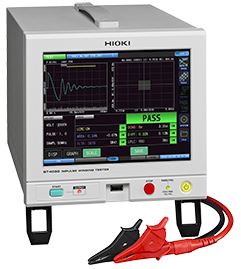
The ST4030 is an impulse winding tester that combines the functions of both a resistance meter and insulation-withstand testing required for electric motor winding manufacturers to improve quality. Meet the needs of more reliable motor windings in light of the increasing use of electric vehicles and self-driving technology.
คุณลักษณะเฉพาะ
- Identify previously undetectable defects • Detect waveforms with high precision (200 MHz high speed sampling × high 12-bit resolution) • Identify single-fault turns via quantification of response waveforms
- Diagnose defective insulation (pseudo-shorts) between motor windings by testing for microscopic partial discharges hidden in noise (option)
Model No. (Order Code)
| ST4030 |
|---|
Note: The Discharge Detection Upgrade ST9000 is a factory option for the Impulse Winding Tester ST4030. Please specify at time of order.
Hioki ST4030 Impulse Winding Tester – Introductory Video
The Impulse Winding Tester ST4030 identifies the LC and RC characteristics from the response waveform when a coil is measured. Because the circuit constant value can be treated quantitatively, users can clearly define the threshold values against which to determine the pass/fail condition of coils based on numerical data. In addition, because the test results are in numerical terms, data can be further utilized statistically as a method of quality control. Accumulated data from each fault can be fed back to upstream processes to predict conditions that would lead to non-compliant windings and contribute to the prevention of future defects.
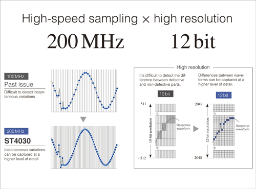
High-precision waveform detection
Slight changes in response waveforms that make it difficult to distinguish the difference between good and defective coils can be detected with a high level of precision. The 200MHz high-speed sampling captures sudden changes with remarkable detail, and the 12-bit high resolution provides the clear differences between the waveforms.
Detect shorts among even just a few turns Quantification of response waveforms now make it easy to identify the differences in the coil among even just a few turns, an ability that has been difficult in the past. The LC and RC distribution between compliant and non-compliant products provide a clear criterion to make informed decisions.
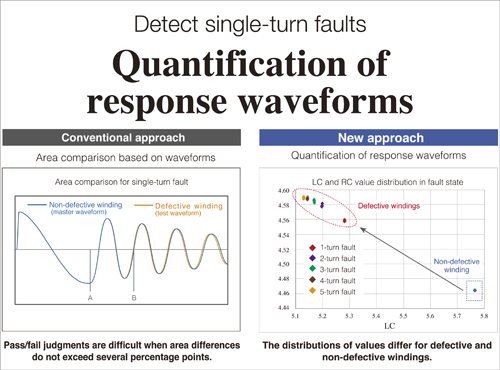
Detect hard to identify shorts among even just a few turns
Quantification of response waveforms now make it easy to identify the differences in the coil among even just a few turns, an ability that has been difficult in the past. The LC and RC distribution between compliant and non-compliant products provide a clear criterion to make informed decisions.
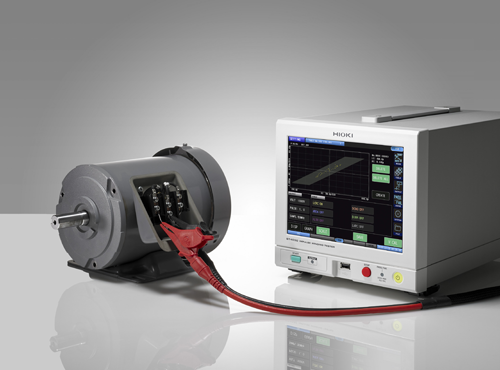
Testing after rotor assemblyTesting after rotor assembly
Once the rotor has been attached to the motor’s stator, the stray capacitance between the rotor and stator will vary depending on the position at which the rotor was attached. This variation in stray capacitance means that the response waveform obtained during impulse testing varies, preventing use of the conventional waveform comparison method. Although the LC and RC values used to quantify response waveforms also vary due to variations in those waveforms, the distributions of those values vary for defective and non-defective parts. Consequently, impulse testing can be performed after the rotor has been installed as long as defective and non-defective part judgment areas have been created.
How to Use the Hioki Impulse Winding Tester ST4030
The ST4030 detects the existence of layer shorts between coil windings, defects that are found in motor inductors. By using a master waveform taken from a reference coil after applying an impulse voltage, and comparing it to the measured waveform across a specific interval of the coil under test, the resulting area difference can help determine pass or fail easily and accurately. In addition, quantification of response waveforms, a new method developed by Hioki, lets you detect even single-turn faults by using a pass/fail distribution plot. Watch this video to learn how to easily make settings and begin testing right away.
Basic specifications (Accuracy guaranteed for 1 year, Post-adjustment accuracy guaranteed for 1 year)
| Measurement items | • Quantification (LC value, RC value) of the response waveform obtained when impulse voltage is applied, pass / fail judgment • Waveform judgment using AREA value, Flutter, Laplacian etc. • Equipped with dielectric breakdown voltage test function |
|---|---|
| Applied voltage | 100 V to 3300 V (Setting resolution: 10 V steps) Maximum applied energy: approx. 55 mJ |
| Testable inductance range | 10 μH to 100 mH |
| Sampling | 200 M / 100 M / 50 M / 20 M / 10 MHz, Resolution: 12 bits, Number of data: 1001 to 800 points (1000 point steps) |
| Voltage detection accuracy | [DC accuracy] ± 5% of setting, [AC band] 100 kHz: ± 1 dB |
| Determination method | LC · RC value judgment, waveform judgment, discharge judgment (when incorporating the ST9000) |
| Number of test condition tables | 255 (test condition setting, judgment condition setting, master waveform) |
| Test time | About 60 ms (3000 V, 1 pulse, reference value at decision OFF) |
| Display | 8.4-inch SVGA color TFT liquid crystal (800 × 600 dots), touch panel |
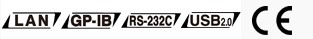
| Interface | Standard: EXT.I/O, USB host (memory), USB device (communication), LAN Optional: RS-232C (Z3001), GP-IB (Z3000) |
| Power supply | 100 V to 240 V AC, 50/60 Hz, 80 VA max. |
| Dimensions and mass | 215 mm (8.46 in)W × 200 mm (7.87 in)H × 348 mm (13.7 in)D, 6.7 kg (236.3 oz) |
| Accessories | Power cord ×1, Instruction Manual ×1, Application disc ×1, Usage notes ×1 |
แค็ตตาล็อก
| แค็ตตาล็อก: IMPULSE WINDING TESTER ST4030 | Download PDF [3MB] | English |